1. Single Legged Routing Mode Example
A typical Web Server Network
A typical network configuration of a web server connected to the Internet looks like this (switches not shown):
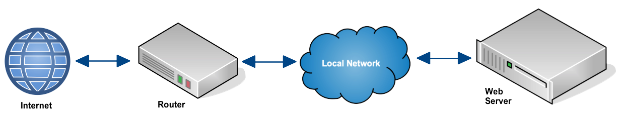
Network configuration before deploying BalanceNG
For this example let’s assume the following IPv4 network parameters are valid within the local network:
Network address:   172.16.1.0/24
Broadcast address: 172.16.1.255
Netmask:           255.255.255.0
The Web server has the IP address 172.16.1.10 with a web server program like Apache listening on Port 80. The default route of this box is set to 172.16.1.254, which is the address that the router offers as a routing endpoint address towards the local network.
Things that obviously work:
- You should be able to ping the default gateway 172.16.1.254 from the Web Server.
- Clients from the Internet are able to initiate TCP connection to port 80 on the Web Server 172.16.1.10.
Adding Load Balancing with BalanceNG
Step 1: Adding a second IPv4 network to the same Layer 2 LAN
The key point of the approach in this example is that a second IPv4 network is being added on the same Layer 2 infrastructure. At the first glance one might feel uncomfortable with this, which is unnecessary. The switches in the LAN simply don’t care about the higher level protocol layers with the IPv4 or IPv6 addresses contained in the packets.
Let’s imagine we are adding the following network parameters:
Network address:   10.1.1.0/24
Broadcast address: 10.1.1.255
Netmask:           255.255.255.0
Step 2: Duplicating the Web Server functionality and assigning addresses in that new network
- Both new web servers need to serve exactly the same contents
- Web Server A now listens on address 10.1.1.1, and the other on 10.1.1.2 (both on port 80 as for this example)
- The default gateway on both web servers points to 10.1.1.254 (which will be represented by BalanceNG)
Step 3: Adding BalanceNG running on an extra machine
After adding an extra BalanceNG machine the new network looks like this:
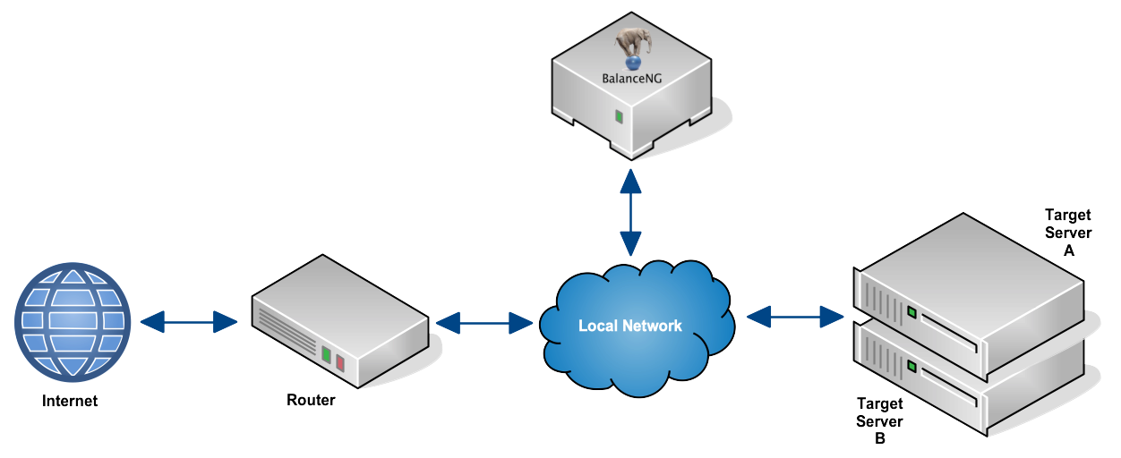
Network configuration before deploying BalanceNG
The BalanceNG configuration bng.conf looks like this:
//        configuration taken ...
//        BalanceNG ...
modules   vrrp,arp,ping,hc,master,slb,tnat,nat,rt
set       ipforwarding 1
interface 1 {
          name eth0
          access raw
}
register  interface 1
enable    interface 1
network   1 {
          name "local network"
          addr 172.16.1.0
          mask 255.255.255.0
          real 172.16.1.252
          virt 172.16.1.253
          nat outside
          interface 1
}
network   2 {
          name "target network"
          addr 10.1.1.0
          mask 255.255.255.0
          real 10.1.1.253
          virt 10.1.1.254
          nat inside
          interface 1
}
register  networks 1,2
enable    networks 1,2
gateway   {
          ipaddr 172.16.1.254
          ping 3,8
}
server    1 {
          ipaddr 172.16.1.10
          port 80
          protocol tcp
          targets 1,2
}
register  server 1
enable    server 1
target    1 {
          ipaddr 10.1.1.1
          port 80
          protocol tcp
          tcpopen 80,3,10
}
target    2 {
          ipaddr 10.1.1.2
          port 80
          protocol tcp
          tcpopen 80,2,10
}
register  targets 1,2
enable    targets 1,2
//        end of configuration
Let’s have a look at some of the important parts:
- The two network sections are using the same interface (interface 1).
- The gateway section is referencing the router as before.
- The former IPv4 address 172.16.1.10 is now represented by BalanceNG.
- The two web servers are now referenced as target servers using IPv4 addresses within the new IPv4 network.
- The network 2 virt 10.1.1.354 configuration directive declares the routing endpoint for the target servers.
- The declarations nat inside and nat outside establish NAT for any other communication.
Step 4: Testing
- You should be able to ping the default gateway 10.1.1.254 from the target servers.
- You should be able to ping the virtual web server 172.16.1.10 from the router.
- Clients from the Internet should be able to initiate TCP connection to port 80 on the virtual Web Server 172.16.1.10 (now being represented by BalanceNG).
- “show servers” and “show targets” in BalanceNG interactive mode should show everything up and operational.